HPE StoreVirtual VSA Software & Components

ارسال شده توسط admin | در دسته بندی Uncategorized

HPE StoreVirtual VSA Software & Components


HPE StoreVirtual VSA Software transforms your server’s internal or direct-attached storage into a fully-featured shared storage array without the cost and complexity associated with dedicated storage. StoreVirtual VSA is a virtual storage appliance optimized for VMware vSphere.  StoreVirtual VSA creates a virtual array within your application server and scales as storage needs evolve, delivering a comprehensive enterprise-class feature set that can be managed by an IT generalist. The ability to use internal storage within your environment greatly increases storage utilization. The unique scale-out architecture offers the ability to add storage capacity on-the-fly without compromising performance. Its built-in high availability and disaster recovery features ensure business continuity for the entire virtual environment.

Simple and Flexible to Manage

Enjoy all the benefits of traditional SAN storage without a dedicated storage device. HPE StoreVirtual VSA Software allows you to build enterprise level, highly available, shared storage functionality into your server infrastructure to deliver lower cost of ownership and superior ease of management.

All StoreVirtual VSA nodes in your environment, onsite or across multiple sites, can be managed from the Centralized Management Console (CMC). The CMC features a simple, built-in best practice analyzer and easy-to-use update process. Add more internal storage capacity to the cluster by simply adding servers with StoreVirtual VSA installed. No external storage device required: Create shared storage out of internal or external disk capacity (DAS, SAN); (FC or iSCSI).

Snapshots provide instant, point-in-time volume copies that are readable, writeable, and mountable for use by applications and backup software. Avoid data loss of any single component in a storage node with StoreVirtual’s multi-fault protection. Remote Copy enables centralized backup and disaster recovery on a per-volume basis and leverages application integrated snapshots for faster recovery.

Network RAID stripes and protects multiple copies of data across a cluster of storage nodes, eliminating any single point of failure in the StoreVirtual array. Applications have continuous data availability in the event of a disk, controller, storage node, power, network, or site failure. Create availability zones within your environment across racks, rooms, buildings, and cities and provide seamless application high availability with transparent failover and failback across zones—automatically.
Increase Scalability and Storage Efficiency

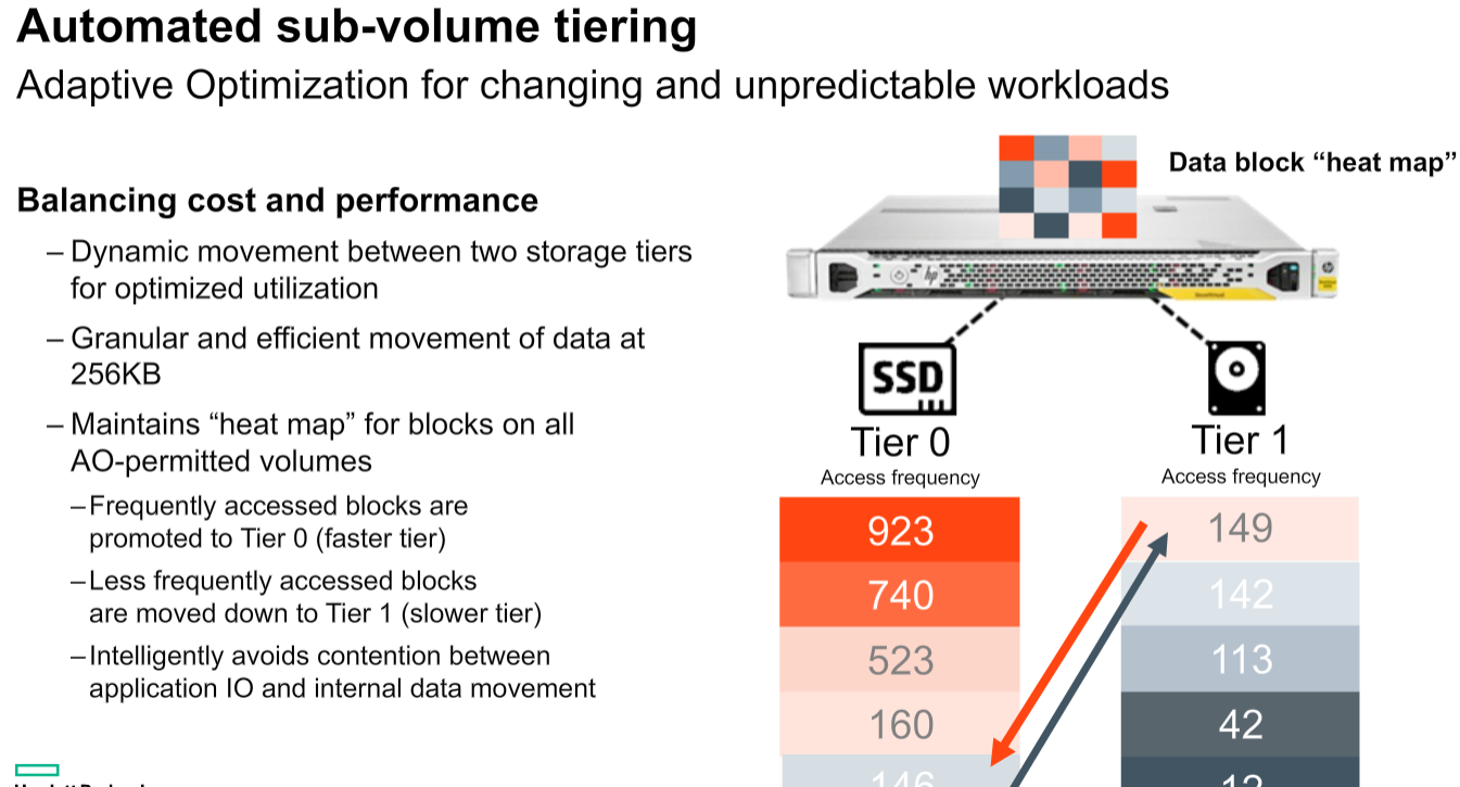
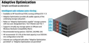
Use StoreVirtual VSA with solid-state drives (SSDs) to provide a high-performance storage solution in your environment. Create an all-flash tier for maximum performance or use a lower cost alternative with StoreVirtual Adaptive Optimization to create automated tiers with an optimized amount of SSDs. Maximize storage utilization by deploying high-performance arrays at the main site and cost-effective appliances at remote sites. Use management plug-ins for VMware vCenter. Lower storage costs and achieve high availability with as few as two nodes that easily scale from within Scale-out storage architecture allows the consolidation of internal and external disks into a pool of shared storage. All available capacity and performance is aggregated and accessible to every volume in the cluster. As storage needs grow, the cluster scales out linearly while remaining online.

Components

Built on an open-standards platform, StoreVirtual VSA software can run on any modern x86-based hardware in VMware vSphere, Microsoft Hyper-V, and Linux KVM hypervisors.

StoreVirtual technology components include targets (storage systems and storage clusters) in a networked infrastructure. Servers and virtual machines act as initiators with access to the shared storage. The LeftHand OS leverages industry-standard iSCSI protocol over Ethernet to provide block-based storage to application servers on the network. And for high availability it uses fail over manager or Quorum Disk’s.

HPE Store Virtual Software

HP StoreVirtual VSA is a proper virtual storage appliance (VSA) suppor

ted in production environments providing block-based storage via iSCSI.

A VSA is a virtual appliance deployed in a VMware environment which aggregates and abstracts physical underlying storage in a common storage pool which will be presented to the hypervisor and can be used to store virtual machine disks and related files.

StoreVirtual VSA can use both existing VMFS datastores and RDM (raw LUNs) to store data and it can be configured to support sub-volume tiering to move data chunks across tiers. StoreVirtual VSA as the “physical” HP StoreVirtual counterpart is a scale-out solution, this means that if you need to increase storage capacity, resilience or performance other StoreVirtual VSA nodes (i.e. virtual appliances) can be deployed.

Storage System or Storage Node

A storage node is a server that virtualizes its direct-attached storage. In the case of StoreVirtual nodes, each one includes controller functionality—no external controllers needed. Storage nodes require minimal user configuration to bring them online as available systems within the Centralized Management Console (CMC).

StoreVirtual Cluster

Multiple StoreVirtual VSAs running on multiple servers create a scalable pool of storage with the ability to make data highly available. We can aggregate two or more storage nodes into a flexible pool of storage, called a storage cluster.

Multiple clusters can be aggregated together into management groups. Volumes, clusters and management groups within the shared storage architecture can be managed centrally through a single console.

Management groups

A Management Group is a logical container which allow the management of one or more HP StoreVirtual VSAs, Clusters and Volumes. Management group will have credentials set on the configuration time .And these credentials will be used for any management task of any HP StoreVirtual belonging to this specific Management Group.

FOM & Quorum Disk

The Failover Manager (FOM) is designed to provide automated and transparent failover capability. For fault tolerance in a single-site configuration, the FOM runs as a virtual appliance in either a VMware vSphere, Microsoft Hyper-V Server, or Linux KVM environment, and must be installed on storage that is not provided by

the StoreVirtual installation it is protecting.

The FOM participates in the management group as a manager; however, it performs quorum operations only, it does not perform data movement operations. It is especially useful in a multi-site stretch cluster to manage quorum for the multi-site configuration without requiring additional storage systems to act as managers in the sites. For each management group, the StoreVirtual Management Group Wizard will set up at least three management devices at each site. FOM manages latency and bandwidth across these devices, continually checking for data availability by comparing one online node against another.

If a node should fail, FOM will discover a discrepancy between the two online nodes and the one offline node – at which point it will notify the administrator. This process requires at least three devices, with at least two devices active and aware at any given time to check the system for reasonableness: if one node fails, and a second node remains online, the FOM will rely on the third node to maintain quorum, acting as a “witness” to attest that the second node is a reliable source for data.

In smaller environments with only two storage nodes and no third device available to provide quorum, we can implement with any one of the below two option.

  1. Supply a third node onsite with StoreVirtual VSA installed and use FOM to maintain quorum
  2. Set up 2-Node Quorum on a shared disk, using LeftHand OS 12.5 or later versions

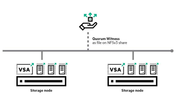
StoreVirtual 2-Node Quorum is a mechanism developed to ensure high availability and transparent failover between 2-node management groups in any number of satellite sites, such as remote offices or retail stores. A cost-effective, low-bandwidth alternative to the FOM, the feature does not require a virtual machine in that site, relying instead on a centralized Quorum Witness in the form of an NFSv3 file share as the tie-breaker between two storage nodes as shown below .

Quorum Witness uses a shared disk to determine which of the two nodes should be considered a reliable resource in the event of a failure. The shared disk is an NFS share that both nodes in the management group can access.

Volume

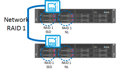
It is basically a shared volume crated with help of Network Raid protection. Network RAID (so the data protection level) can be set per volume. So multiple volumes can co-exist on a StoreVirtual cluster with different Network RAID levels. This Volume can be accessed through iSCSI protocol.

Network RAID protection which basically spreads data between different VSAs as the common RAID spreads data across different physical disks within the same array.

CMC (HP StoreVirtual Centralized Management Console)

All StoreVirtual VSA nodes in your environment, onsite or across multiple sites, can be managed from the Centralized Management Console (CMC). The CMC features a simple, built-in best practice analyzer and easy-to-use update process
0 دیدگاه | سپتامبر 28, 2019

HP StoreVirtual Storage VSA Installtion & Configuration

ارسال شده توسط admin | در دسته بندی Uncategorized

HP StoreVirtual Storage VSA Installtion & Configuration


Continue of Part 1

  • Select the host name / IP address of the ESXI host from drop down menu and click Next

Note:-You may see the Datastore information form this window.

  • Select the HPE Storevirtual VSA and sub two options as shown in the below image and click Next

  • Select the Data store and click next to install the VSA appliance which the VSA should reside

  • Provide the Name for VSA – Appliance , Select the NIC , inut the IP Address and VM port group for communicating to Public Network and Click Next .This step covers the NIC setup of the VSA. Recommended to use two NICs for the VSA: One for management and a second one for iSCSI traffic .

  • Give a name to the VM and to select the drive type , Prefer same as Appliance DNS Name

Note: – Since there is no RDMs currently the option is greyed out.

  • Now we have to configure the data disks .This Data disks will be used for creating shared volume for ESXi hosts.

Note: – Also we can configure the Tiering, Select the Data store, Size and Tier, Tiering will be on differ type of disks like SSD, SAS or NL SAS. If have to use AO (Adaptive Optimization) Tiering should be configured. Refer # Step

  • Select No, I am done and click next , this option will deploy the Appliance

  • Before you click Deploy check the settings of Appliance. If everything is fine, click the Deploy button. The deployment will start immediately

  • Deployment started and it may take few minutes to complete.

  • Once the deployment is finished, Click “Finish”. Start the Centralized Management Console (CMC) and add the VSA nodes. If CMC already installed you may close the wizards else CMC is installed automatically by the wizard.

Continue PART 3 

See – Part 1  ,  PART 2 ,  PART 4  

0 دیدگاه | سپتامبر 28, 2019

HP StoreVirtual Storage VSA Installtion & Configuration – PART 1

ارسال شده توسط admin | در دسته بندی Uncategorized

HP StoreVirtual Storage VSA Installtion & Configuration – PART 1


Installing the CMC

Install the CMC on the computer or virtual machine that you use to administer the HP StoreVirtual Storage. You administer the entire network of StoreVirtual VSAs from this CMC.
To obtain the CMC, download the CMC installer from the following website

The CMC installation requires 63 MB disk space and 64 MB RAM during runtime. Installing the CMC in Microsoft Windows
1. Start the CMC installer.
2. Follow the steps in the installation wizard.
3. When the installation completes, HP is added as a separate Program Group and a shortcut icon is added to the  microsoft Windows desktop.
To start the CMC:
• Double-click the icon on your desktop, or
• From the Start menu, select
All Programs→HP →HP StoreVirtual→HP StoreVirtual Centralized Management Console


Installing the HP StoreVirtual VSA for vSphere

The HP StoreVirtual VSA for vSphere is pre-formatted for use with VMware vSphere. We have to install VSA on all the ESXi hosts.

Download the StoreVirtual OS 12.5 from below link .And follow steps mentioned below to install and Configure VSA on vSphere Host.

Required version of VMware

  • VMware vSphere 6.0 for LeftHand OS 12.5

Configuration requirements for the StoreVirtual VSA for vSphere

  • Virtual disk(s) with up to 64 TB (for vSphere 6.0) of space per disk located on internal disk storage, or any block storage that is on the VMware HCL: internal, external and shared. (Note that the LeftHand OS software consumes a small amount of the available space.)
  • StoreVirtual VSA for vSphere virtual disks must be configured as independent and persistent to prevent VM snapshots from affecting them.
  • The VMFS datastores for the StoreVirtual VSA must not be shared with any other VMs.
  • Microsoft NET 3.5 on the installer client.
  • vCenter servers properly licensed before connecting to them using the HP StoreVirtual VSA for vSphere installer.
  • When installing StoreVirtual VSAs that use more than 8 TB of datastores, increase the VMFS heap size. According to VMware, the VMFS heap size must be increased to access more than 8 TB of VMDKs in a VM. This means that a StoreVirtual VSA that uses more than 8 TB of datastores should have the heap size increased. See the following article for more information:

Reference KB

Best practices for StoreVirtual VSA for vSphere

  • Configure the StoreVirtual VSA for vSphere to start automatically and first, and before any other virtual machines, when the vSphere Server on which it resides is started. This ensures that the StoreVirtual VSA for vSphere is brought back online as soon as possible to automatically re-join its cluster.
  • Locate the StoreVirtual VSA for vSphere on the same virtual switch as the VMkernel network used for iSCSI traffic. This allows for a portion of iSCSI I/O to be served directly from the StoreVirtual VSA for vSphere to the iSCSI initiator without using a physical network.
  • Locate the StoreVirtual VSA for vSphere on a virtual switch that is separate from the VMkernel network used for VMotion. This prevents VMotion traffic and StoreVirtual VSA for vSphere I/O traffic from interfering with each other and affecting performance.
  • HP recommends installing vSphere Server on top of a redundant RAID configuration with a RAID controller that has battery-backed cache enabled. Do not use RAID 0.

Unsupported configurations for StoreVirtual VSA for Hyper-V

  • Use of Microsoft Live Migration, Quick Migration, or snapshots on the StoreVirtual VSA itself.
  • Use of any Hyper-V Server configuration that Microsoft does not support.
  • Extending the data virtual disk(s), the first SCSI Controller in Hyper-V, of the StoreVirtual VSA while in a cluster. Create additional disks and hot-add them instead.
  • Co-location of a StoreVirtual VSA and other virtual machines on the same NTFS partition.
  • Running StoreVirtual VSA for Hyper-Vs on top of existing HP StoreVirtual Storage is not recommended.

Deploying HP StoreVirtual

As mentioned above once you have completed the download from the webpage you may found downloaded File will be named like below

HPE_StoreVirtual_VSA_2014_and_StoreVirtual_FOM_Installer_for_VMware_vSphere_TA688-10544.exe

  • Ran this file as Administrator, it is a self-extracting one. After the extraction a CMD will comes up asking, if you want to use the GUI or CLI interface.
  • Chose the GUI wizard.
  • On the welcome page simply click “Next”.
  • Accept the License Agreement and Click Next


Continue  PART 2 

See – Part 1  PART 3  ,  PART 4  

0 دیدگاه | سپتامبر 28, 2019

HP StoreVirtual Storage VSA Installtion & Configuration

ارسال شده توسط admin | در دسته بندی Uncategorized

HP StoreVirtual Storage VSA Installtion & Configuration


Continue of Part 1

  • Select the host name / IP address of the ESXI host from drop down menu and click Next

Note:-You may see the Datastore information form this window.

  • Select the HPE Storevirtual VSA and sub two options as shown in the below image and click Next

  • Select the Data store and click next to install the VSA appliance which the VSA should reside

  • Provide the Name for VSA – Appliance , Select the NIC , inut the IP Address and VM port group for communicating to Public Network and Click Next .This step covers the NIC setup of the VSA. Recommended to use two NICs for the VSA: One for management and a second one for iSCSI traffic .

  • Give a name to the VM and to select the drive type , Prefer same as Appliance DNS Name

Note: – Since there is no RDMs currently the option is greyed out.

  • Now we have to configure the data disks .This Data disks will be used for creating shared volume for ESXi hosts.

Note: – Also we can configure the Tiering, Select the Data store, Size and Tier, Tiering will be on differ type of disks like SSD, SAS or NL SAS. If have to use AO (Adaptive Optimization) Tiering should be configured. Refer # Step

  • Select No, I am done and click next , this option will deploy the Appliance

  • Before you click Deploy check the settings of Appliance. If everything is fine, click the Deploy button. The deployment will start immediately

  • Deployment started and it may take few minutes to complete.

  • Once the deployment is finished, Click “Finish”. Start the Centralized Management Console (CMC) and add the VSA nodes. If CMC already installed you may close the wizards else CMC is installed automatically by the wizard.

Continue PART 3 

See – Part 1  ,  PART 2 ,  PART 4  

0 دیدگاه | سپتامبر 28, 2019

Deployment Of FOM (Failover Manager)

ارسال شده توسط admin | در دسته بندی Uncategorized

Deployment Of FOM (Failover Manager)


Use the Same file which used for Deployment of VSA Applianace

HPE_StoreVirtual_VSA_2014_and_StoreVirtual_FOM_Installer_for_VMware_vSphere_TA688-10544.exe

  • Ran this file as Administrator, it is a self-extracting one. After the extraction a CMD will comes up asking, if you want to use the GUI or CLI interface.

  • Chose the GUI wizard.
  • On the welcome page simply click “Next”.

  • Accept the License Agreement and Click Next


  • Provide hostname or IP address and login credentials for the target the vCenter server and click Next

  • Select the host name / IP address of the ESXI host from drop down menu and click Next


  • Select the HPE Storevirtual FOM as shown in the below image and click Next

  • Select the Data store and click next to install the Failover Manager (FOM)

Note: You must select the Storage that is not provided by the Storevirtual installation it is protecting.

  • Provide the Name for FOM, Select the NIC & input the IP Address and VM port group for communicating to Public Network and Click Next.

  • Give a name to the VM and to select the drive type

  • The wizard allows to deploy FOM.

Note: – There will be a pop-up message for before deployment as shown in the below image

  • Before you click Deploy check the settings of Appliance. If everything is fine, click the Deploy button. The deployment will start immediately

  • Deployment started and it may take few minutes to complete

Once the deployment is finished, Click “Finish”. Start the Centralized Management Console (CMC) and add the FOM nodes.

Continue PART 4  

See – Part 1  ,  PART 2  , PART 3  ,

0 دیدگاه | سپتامبر 28, 2019

3 PAR Multipathing Best Practice With VSphere 6.5

ارسال شده توسط admin | در دسته بندی Uncategorized

3 PAR Multipathing Best Practice With VSphere 6.5


Why Multipathing ?

To maintain a constant connection between a host and its storage, ESXi supports multipathing. Multipathing is a technique that lets you use more than one physical path that transfers data between the host and an external storage device.

In case of a failure of any element in the SAN network, such as an adapter, switch, or cable, ESXi can switch to another physical path, which does not use the failed component. This process of path switching to avoid failed components is known as path failover.

In addition to path failover, multipathing provides load balancing. Load balancing is the process of distributing I/O loads across multiple physical paths. Load balancing reduces or removes potential bottlenecks.

To take advantage of this support, virtual volumes should be exported to multiple paths to the host server. For this we have to create a host definition on the HPE 3PAR Storage system that includes the World Wide Names (WWNs) of multiple HBA ports on the host server and then export the VLUNs to that host definition. For an ESXi cluster, the VLUNs must be exported to all of the host definitions for the cluster nodes, or a host set may be created containing all of the servers and the VLUNs.

Setting Round Robin path policy

VMware vSphere includes active/active multipath support to maintain a constant connection between the ESXi host and the HPE 3PAR StoreServ Storage array. Three path policies are available,

Fixed (VMware)

The host uses the designated preferred path, if it has been configured. Otherwise, it selects the first working path discovered at system boot time. If you want the host to use a particular preferred path, specify it manually. Fixed is the default policy for most active-active storage devices.

Note
If the host uses a default preferred path and the path’s status turns to Dead, a new path is selected as preferred. However, if you explicitly designate the preferred path, it will remain preferred even when it becomes inaccessible.

Most Recently Used (VMware)

The host selects the path that it used most recently. When the path becomes unavailable, the host selects an alternative path. The host does not revert back to the original path when that path becomes available again. There is no preferred path setting with the MRU policy. MRU is the default policy for most active-passive storage devices.

Round Robin (VMware)

The host uses an automatic path selection algorithm rotating through all active paths when connecting to active-passive arrays, or through all available paths when connecting to active-active arrays. RR is the default for a number of arrays and can be used with both active-active and active-passive arrays to implement load balancing across paths for different LUNs.

For HPE 3PAR storage, Round Robin is the recommended policy for best performance and load balancing; however, it may not be enabled by default. The path policies can be viewed and modified from the VMware vSphere Web Client on a per datastore basis as follows:

  1. In the vSphere Web Client, select the datastore.
    2. Select the Manage tab, then the Settings tab, and then click on Connectivity and multipathing
    3. Select one of the ESXi hosts and then click the Edit Multipathing button.
    4. In the pop-up window, select Round Robin from the Path selection policy drop-down menu.
    5. Click the OK button to save the new setting.
    6. Repeat steps 3 through 5 for each ESXi host.


Below Picture shows HPE 3PAR StoreServ Fast Class VLUN that has most recently used  and active IO only on one path .

Change the policy to Round Robin path  and check the status of “Active (I/O)” , it will be like below


Setting IOPS option for Round Robin policy

Managing a Round Robin I/O path policy scheme through the vSphere Web Client on a per datastore will not allow setting . We can modify the Round Robin policy details from command line on the ESXi host. To achieve better load balancing across paths,the –iops option may be issued on the command line to specify that the path should be switched after performing the specified number of I/Os on the current path. By default, the –iops option is set to 1000. The recommended setting for HPE 3PAR Storage is 1, and this setting may be changed as needed to suit the demands of various workloads.

Set the Round Robin policy for a specific device


# esxcli storage nmp device set –device <device-name> –psp VMW_PSP_RR


To set the device specified by –device to switch to the next path after 1 I/O operation has been performed on the current path


# esxcli storage nmp psp roundrobin deviceconfig set –type=iops –iops=1 –device <device-name>


Automating Round Robin policy for all LUNs

To automate this we have to edit the SATP rule or created using esxcli commands on the ESXi host to automatically achieve aRound Robin path policy for newly discovered LUNs.

Use the following command to create a custom SATP rule that will allow the ESXi host to configure the HPE 3PAR LUNs to use Round Robin multipath policy. The command must be executed on each ESXi host that is connected to the HPE 3PAR array.


#esxcli storage nmp satp rule add -s “VMW_SATP_ALUA” -P “VMW_PSP_RR” -O “iops=1” -c “tpgs_on” -V “3PARdata” -M “VV” -e “HP 3PAR Custom Rule”


Verify the new rule using the following command:


# esxcli storage nmp satp rule list | grep “3PARdata”


Note:New rule will be effective when adding new devices to the ESXi host, For existing LUNs, either a host reboot is required, or the path policy must be set for each LUN.

Reference

0 دیدگاه | سپتامبر 28, 2019

How To Install Or Update The License On 3PAR Storage System

ارسال شده توسط admin | در دسته بندی Uncategorized

There are two Ways you can apply the license to 3PAR Storage one is from GUI and other is from CLI .
Before proceeding the steps make sure you have proper license file or license detils .You can obtain the license file from HP reseller or HP Portal or Hp Account Manager

In this post we are sharing information how can you apply license to you 3 PAR storage , follow below procedure

How to Apply License From GUI

Open HP 3PAR Management Console and Login

After Login On the Left pane you can see your 3PAr storage system

Right Click on the Storage System and select Set license

Once the License window opens you will have two option to add license , select the appropriate way and select the Agree to the terms and conditions and Click OK 

License File  – Browse the license file FILE.DAT which we received form HPE or Downloaded from HPE License Site

License Key  – License Key is a combination of numbers and letter you can copy form your source and paste there .

Once Apply the License you can Navigate to the software tab and check the license features from there .


You can check the License status from the CLI  by entering the command showlicense , check below image you can see before and after applying license difference

How to Apply License From CLI

Open the 3PAR Console using putty

Use the command setlicense to apply new license to upgrade

Once enter the set license command it will ask you confirm that agree to the terms and conditions by selecting Y for proceed to add license .

You can add the license keys on the CLI window and enter once again as empty line and license will applied


Click here to access the portal for HPE Licensing.

OR

Click here to access the portal for License Support Centers.

0 دیدگاه | سپتامبر 28, 2019

EMC VNX Components And Their Purpose

ارسال شده توسط admin | در دسته بندی Uncategorized

EMC VNX Components And Their Purpose


Components and their purpose

Standby Power Supply – SPS – This is a 1u uninterruptible power supply designed to hold the Storage processors during a power failure for long enough to write any data in volatile memory to disk.

Disk Processor Enclosure – DPE (VNX5100/5300/5500/5200/5400/5600/5800/7600 models) – This is the enclosure that contains the storage processors as well as the Vault Drives and a few other drives. It contains all connections related to block level storage protocols including Fiber Channel and iSCSI.

Storage Processor Enclosure – SPE (VNX5700/7500/8000 models) – This is the enclose that contains the storage processors on the larger VNX models. It is in place of the DPE mentioned above.

Storage Processor – SP –  Usually followed by “A” or “B” to denote if which one it is, all VNX systems have 2 storage processors. It is the job of the storage processor to retrieve data from the disk when asked, and to write data to disk when asked. It also handles all RAID operations as well as Read and Write caching. iSCSI and additional Fiber Channel ports are added to the SP’s using UltraFlex modules.

UltraFlex I/O Modules – These are basically PCIe Cards that have been modified for use in a VNX system. They are fitted into a metal enclosure that is then inserted into the back of the Storage Processors or Data Movers, depending on if it is for Block or File use.

Control Station – CS –  Normally preceded by “Primary” or “Secondary” as there are at least 1, but most often 2 control stations per VNX system. It is the job of the control station to handle management of the File or Unified components in a VNX system. Block only VNX arrays do not utilize a control station. However in a Unified or File only system the Control stations run Unisphere and pass any and all management traffic to the rest of the array components.

 Data Mover Enclosure – Blade Enclosure – This enclosure houses the data movers for file and unified VNX arrays.

Data Movers – X-Blades – DM – Data movers  (aka X-Blades) connect to the storage processors over dedicated fiber channel cables and provide File (NFS, pNFS, and CIFS) access to clients. Think of a data mover like a linux system which has SCSI drives in it, it then takes those drives and formats them with a file system and presents them out one or more protocols for client machines to access.

Disk Array Enclosure – DAE – DAE’s come in several different flavors, 2 of which are depicted in the quick reference sheet. One is a 3u – 15 disk enclosure which holds 15 – 3.5″ disk drives; the second is a 2u – 25 disk enclosure which holds 25 – 2.5″ disk drives; and finally the third is a 4u – 60 disk enclosure which holds 60 – 3.5″ drives in a pull out cabinet style enclosure. The third type is the more rare and are not normally used unless rack space is at a premium.

0 دیدگاه | سپتامبر 28, 2019

FAST CACHE – EMC VNX

ارسال شده توسط admin | در دسته بندی Uncategorized

FAST CACHE – EMC VNX

EMC FAST Cache technology gives a performance enhancement to the VNX Storage Array by adding FLASH drives as a Secondary Cache, working hand-in-hand with DRAM Cache and enhancing overall Storage Array performance. EMC recommend firstly using available Flash Drives for FAST Cache and then adding Flash Drives as a tier to selected FAST VP pools as required. FAST Cache works with all VNX systems (And also CX4) and is activated by installing the required FAST Cache Enabler. FAST Cache works with traditional Flare LUNs and VP Pools.

Note: FAST Cache is enabled at the Pool wide level and cannot be selective for specific LUNs within the Pool.

The initial configuration is quite simple, after adding the required quantity of drives you can create FAST Cache through the System Properties’ console in Unisphere, which will enable FAST Cache for system wide use:

FC

Create and monitor the initialization status of FAST Cache Using Navicli

naviseccli -h SPA_IP cache -fast -create –disks disks -mode rw -rtype r_1
Check on the status of FAST Cache creation:
naviseccli -h SPA_IP cache -fast -info -status

To enable or disable FAST Cache on a specific VP_POOL from Navicli use below 

naviseccli -h SPA_IP storagepool -modify -name “Pool_Name” -fastcache off

naviseccli -h SPA_IP storagepool -modify -name “Pool_Name” -fastcache on

Check what Pools have FAST Cache enabled/disabled

naviseccli -h SPA_IP storagepool -list -fastcache

Note: FAST Cache configuration requires any modification then it first needs to be disabled. By disabling (destroying) FAST Cache all dirty blocks are flushed back to disk; once FAST Cache has completed disabling then you may re-create FAST Cache with your new configuration.

Configuration Options

FAST Cache configuration options range from 100GB on a CX4-120 to 4.2TB of FAST Cache on a VNX-8000.

CX4 VNX1  VNX2
CX4-120 – 100GB VNX 5100 – 100GB VNX 5200 – 600GB
CX4-240 – 200GB VNX 5300 – 500GB VNX 5400 – 1000GB
CX4-480 – 800GB VNX 5500 – 1000GB VNX 5600 – 2000GB
CX4-960 – 2000GB VNX 5700 – 1500GB VNX 5800 – 3000GB
VNX 7500 – 2100GB VNX 7600 – 4200GB
VNX 8000 – 4200GB

FAST-Cache-MAXs

FAST Cache drives are configured as RAID-1 mirrors and it is good practice to balance the drives across all available back-end buses; this is due to the fact that FAST Cache drives are extremely I/O Intensive and placing more than the recommended maximum per Bus may cause I/O saturation on the Bus. Amount of FAST Cache drives per B/E Bus differs for each system but ideally for a CX/VNX1 system aim for no more than 4 drives per bus and 8 for a VNX2. It is best practice on a CX/VNX1 to avoid placing drives on the DPE or 0_0 that will result in one of the drives being placed in another DAE, for example DO NOT mirror a drive in 0_0 with a drive in 1_0.

The order the drives are added into FAST Cache is the order in which they are bound, with the:
first drive being the first Primary;
the second drive being the first Secondary;
the third drive being the next Primary and so on…

Check the internal private RAID_1 Groups of FAST Cache by from Navicli using below command 

naviseccli -h SPA_IP getrg –EngineeringPassword

Note: Do not mix different drive capacity sizes for FAST Cache, either use all 100GB or all 200GB drive types.

Also for VNX2 systems there are two types of SSD available:

FAST Cache SSD  – These are single-level cell (SLC) Flash drives that are targeted for use with FAST Cache. These drives are available in 100GB and 200GB capacities and can be used both as FAST Cache and as TIER-1 drives in a storage pool.

FAST VP SSD  – These are enterprise Multi-level cell (eMLC) drives that are targeted for use as TIER-1 drives in a storage pool (Not supported as ‘FAST Cache’ drives). They are available in three flavors 100GB, 200GB and 400GB.

FAST Cache Internals

FAST Cache is built on the Unified LUN technology; thus the Data in FAST Cache is as secure as any other LUN in the CX/VNX array. FAST Cache is a nonvolatile storage that survives both power and SP failures and it does not have to re-warm after a power outage either.

There will be a certain amount of DRAM allocated during FAST Cache creation for the IO tracking of FAST Cache known as the ‘Memory Map’. This FAST Cache bitmap is directly proportional to the size of the FAST Cache. The memory allocation is something in the region of 1MB for every 1GB of FAST Cache created. So when FAST Cache is being enabled FLARE will attempt to grab approx 1/3rd the required memory from Read cache and 2/3rds from the Write cache and then re-adjusts the existing DRAM read and write caches accordingly.

With a compatible workload; FAST Cache increases performance by reducing the response time to hosts and provides higher throughput (IOPS) for busy areas that may be under pressure from drive or RAID limitations. Apart from ‘Storage Processors’ being able to cache read and write I/Os; the Storage Processors on the VNX also coalesce writes and pre-fetch reads to improve performance. However, these operations generally do not accelerate random read-heavy I/Os and this is where FAST Cache helps. FAST Cache monitors the storage processors’ I/O activity for blocks that are read or written to multiple times, with the third IO to any block within a 64K extent getting scheduled for promotion to FAST Cache, promotion is handled the same way as writing or reading an IO to a LUN. The migration process operates 24×7 using the ‘Least Recently Used algorithm’ in order to determine which data stays and which goes. The writes continue to be written to DRAM write cache but with FAST Cache enabled those writes are flushed to the Flash drives and so increasing flush speeds.

One important thing to note is that while performance of the VNX increases and IOPS figures increase with workload demands there will be an increase in the SP CPU utilization and this should be monitored. There are recommended guidelines on max throughput figures for particular arrays… more on this later.
It is important to know the type of workload on your LUN; as an example, log files are generally written and read sequentially across the whole LUN, in this scenario the LUN would not be a good candidate for FAST Cache as Flash drives are not necessarily better at serving large block sequential I/O when compared to spinning drives. Also Large block sequential I/O workloads are better served by having large quantities of drives, promoting this type of data to FAST Cache will normally result in the data being served by a lesser quantity of drives thus resulting in a performance reduction. Avoiding using FAST Cache on unsuitable LUNs will help to reduce the overhead of tracking I/O for promotion to FAST Cache.

Best Practice

Below are the  conditions that you should factor when deciding if FAST Cache will be a good fit for your environment:

• VNX Storage Processor Utilization is under 70-percent
• There is evidence of regular forced Write Cache Flushing
• The majority I/O block size is under 64K (OLTP Transactions are typically 8K)
• The disk utilization of RAID Groups is consistently running above 60-70%
• Your workload is predominately random read I/O
• Your production LUNs have a high percentage of read cache misses
• Host response times are unacceptable

0 دیدگاه | سپتامبر 28, 2019

How To Use Unisphere – EMC VNX

ارسال شده توسط admin | در دسته بندی Uncategorized

How To Use Unisphere – EMC VNX

Unisphere is web-enabled software for remote management of storage environment. It has all the extras, like widgets and sortable tables, wizards etc. Unisphere Management Server runs on the Storage Processor (SP) and the Control Station.

To launch a Unisphere you can fire up an Internet browser and type the IP address of either one of the SPs or the Control Station.

Note:- Java should be installed and available on the system / browser .

First Login

Default login/password for EMC VNX Unified system is:
login: sysadmin
password: sysadmin

VNXe

login: admin
password: Password123#

Administration of VNX is performed with the Unisphere graphical user interface (GUI). Administration of the VNX system can also be performed with a command line interface (CLI). File enabled VNX systems use a command line interface to the Control Station for file administrative tasks. Block enabled systems have a host-based Secure CLI software option available for block administrative tasks. The CLI can be used to automate management functions through shell scripts and batch files.

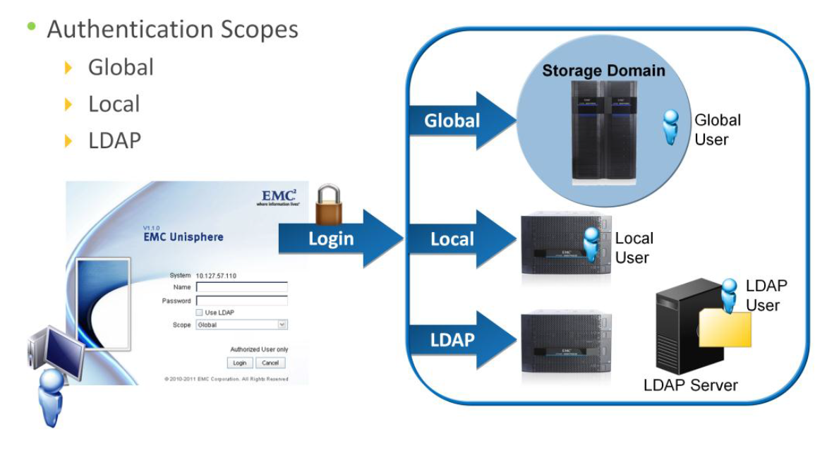
Authentication Scopes

There are three different administrative user auth scopes .

Global authentication scope  :  It is used when the VNX is configured to be a member of a Storage Domain. All the systems within the domain can be administrated using a single sign-on with a global account.
Local authentication scope : It  is used to manage a specific system only. Logging into a system using a local user account is recommended when there are a large number of systems in the domain.
LDAP authentication scope : It  is used when the VNX is configured to “bind” to an LDAP domain. The VNX performs an LDAP query to the domain to authenticate the administrative users.

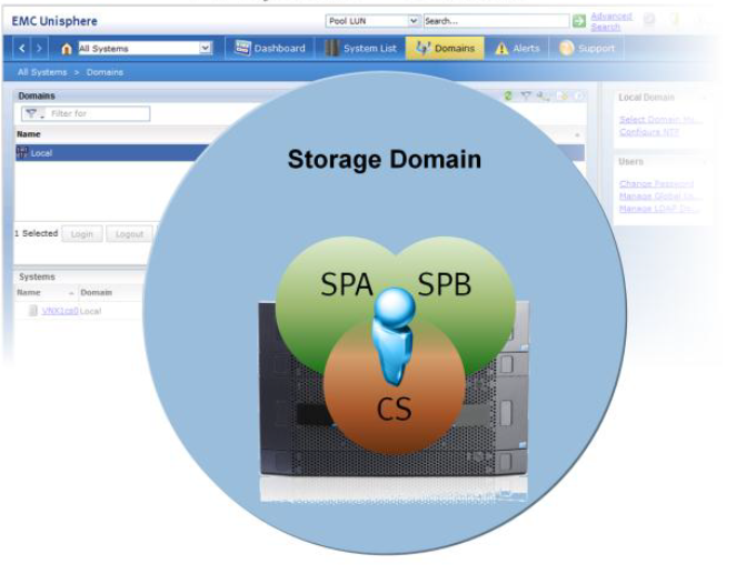
Storage Domains

By default each VNX is its own Storage Domain.

Domain Members are:
* SPA
* SPB
* Control Station
* System managed by Unisphere session to any member

A VNX system can be manager using a Unisphere session to any member of the Storage Domain. The system also includes a default “sysadmin” Global user account in the Domain, which is configured with the Administrator role.

Adding VNX system to Domain

 To add a VNX system into an existing VNX local domain, in Unisphere navigate to the System List, and perform Add operation. You have to provide an SP (Storage Processor) IP address of the VNX system to be added. When adding a system into the domain, the system being added will be removed from any of its existing domain configurations. Obviously you will also be asked for credentials to login to the VNX system being added. Once the VNX system is added, it will be displayed in the System List page.

0 دیدگاه | سپتامبر 28, 2019